Find the correct R1 resistor value for a reflection attenuator with Glofell's online calculator, helping you achieve the desired attenuation and impedance match.
Introduction
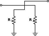
This calculator helps you determine the required termination resistor values for a Reflection Attenuator. Ideally, a reflection attenuator uses a quadrature hybrid coupler terminated with two identical resistors (or variable loads).
The calculator provides two possible resistor solutions based on the system impedance () and the desired attenuation:
To calculate the resistor values, we first determine the Reflection Coefficient () based on the desired Attenuation ().
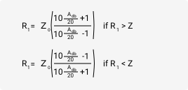
Once we have the reflection coefficient, there are two formulas to find the resistance (), depending on whether the resistance is higher or lower than the characteristic impedance ():
Case 1: (High State)
Case 2: (Low State)
Where:
General Function Attenuators are passive circuits used to reduce the amplitude of a signal without significantly distorting its waveform. They act as a bridge between a high-power source (transmitter) and a sensitive load (receiver/antenna), ensuring the signal level is within a safe operating range.
Why Use Reflection Attenuators? Unlike standard Pi or T-pad attenuators, Reflection Attenuators offer unique advantages in RF design:
An attenuator reduces the power of an RF signal while preserving its waveform. In a reflection attenuator, a quadrature hybrid directs the signal toward a pair of terminating resistors. The resistors reflect part of the power back, and the combination of forward and reflected paths produces the desired attenuation. For example, a 3 dB attenuator causes a signal reflected by the load to pass through the attenuator twice, resulting in 6 dB total return loss.
Enter the desired attenuation in dB and the system impedance Z0. The calculator then applies these formulas: for R1 < Z0, R1 = Z0 * ((10^(dB/20) - 1) / (10^(dB/20) + 1)); for R1 > Z0, R1 = Z0 * ((10^(dB/20) + 1) / (10^(dB/20) - 1)). The second resistor R2 is set equal to R1.
Enter the resistor values R1 and R2 along with the system impedance to compute the attenuation in dB and the resulting input/output impedance. The calculator can also work in reverse, generating R1 and R2 from a required attenuation. Note that loss is usually stated as a positive dB value, though some documents quote return loss as a negative figure, similar to an S11 parameter on a network analyzer.
For a reflection attenuator, the formula for the termination resistance R1 is R1 = Z0 * ((10^(dB/20) - 1) / (10^(dB/20) + 1)) when R1 is less than Z0, and R1 = Z0 * ((10^(dB/20) + 1) / (10^(dB/20) - 1)) when R1 is greater than Z0. R2 is identical to R1.
An attenuator reduces the power of a signal without significantly distorting its waveform. It is the opposite of an amplifier: rather than adding gain, it provides a controlled loss, typically expressed in dB. Attenuators are used to adjust signal levels, improve impedance matching, and protect sensitive components in RF and audio systems.
The source EMF is a property of the signal generator, not the attenuator. To find output levels, calculate the attenuator's input impedance from its resistor network, then apply the source EMF across the combined source and load impedances. In some examples, a source EMF of 2 V is used to simplify voltage calculations.
A 3 dB attenuator is an attenuator that reduces signal power to half its original value, i.e., a 3 dB loss. When placed in front of a load, the signal that reaches the load is 3 dB lower than the input. If the load reflects the signal, it travels through the attenuator again, adding another 3 dB, for a total return loss of 6 dB.
In audio and guitar amplifier applications, an attenuator can influence tone. The effect depends on the attenuator's design, impedance matching, and frequency response. Some units may roll off high frequencies or alter the interaction between the amplifier and speaker. Adjusting the amplifier's EQ or master volume after engaging the attenuator often helps preserve the original tone. High-quality attenuators are designed to minimize tonal coloration.
The best attenuator depends on the application. For RF circuits, key selection criteria include attenuation accuracy, frequency range, power handling, and VSWR. For guitar amps, look for a unit with appropriate wattage, impedance, and transparent tone. There is no single best model; choose one that matches your specific requirements and budget.
RF attenuators are available in several designs: fixed, step, continuously variable, programmable, DC bias, and DC blocking. Important specifications include attenuation (dB), frequency range, power handling (W), and characteristic impedance (Ohms). Selecting the right type depends on whether you need fixed loss, adjustable attenuation, or remote/programmable control.
Resistor Color Code Calculator
Glofell’s Resistor Color Code Calculator decodes 4-band, 5-band, and 6-band resistors. Select each band to identify resistance, tolerance, and power rating for circuit work, repairs, or lab sorting.
Ohms Law Calculator
Glofell’s Ohm’s Law Calculator helps engineers and students quickly solve for voltage, current, resistance, and power. Provide any two known values to calculate the remaining parameters, making it a practical reference for circuit design, troubleshooting, and electronics learning.
Op-Amp Voltage and Gain Calculator
Calculate output voltage together with inverting and non-inverting gain for operational-amplifier circuits. Enter V1, V2, Vp, Vn, and resistor values R1 through R4 to obtain accurate results for circuit design, troubleshooting, and op-amp learning.
Inverting Op-Amp Resistor Calculator
Analyze an inverting operational-amplifier circuit by entering the desired gain, output voltage (Vout), R1 resistance, and input voltages V1, V2, Vp, and Vn. The calculator automatically determines the required R2, R3, and R4 resistor values, helping you design and verify inverting op-amp configurations.