• open navigation menu
  • Logo
    • Input keywords/ Part number
    • Manufacturers
    • Hot Products
    • RFQ
    • Blog
    • Tools
    • About Us
    • Quality Control
    Logo

    Sale support

    • info@glofell.com

    Company

    • Blog
    • About Us
    • Quality Control
    • Contact Us

    Resource

    • Categories
    • Manufacturers
    • Tools

    Quick link

    • Privacy Policy
    • Terms & Conditions
    • Cookies Policy
    • Refund & Return Policy
    • Shipping & Delivery Policy

    © 2026 Copyright. All Rights Reserved. Made by Glofell

    Payment
    Payment
    Payment
    Payment
    1. Home/
    2. Tools/
    3. Inverting Op-Amp Resistor Calculator

    Inverting Op-Amp Resistor Calculator

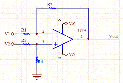
    Analyze an inverting operational-amplifier circuit by entering the desired gain, output voltage (Vout), R1 resistance, and input voltages V1, V2, Vp, and Vn. The calculator automatically determines the required R2, R3, and R4 resistor values, helping you design and verify inverting op-amp configurations.

    Input Parameters
    V
    KOhms
    V
    V
    V
    V
    Outputs
    KOhms
    KOhms
    KOhms
    Op-Amp Circuit Schematic

    Introduction

    Op-Amp Inverting Amplifier Circuit Design & Calculator Guide

    1. OP AMP Resistor Calculator Overview

    The OP AMP Resistor Calculator is a professional design tool used to determine the correct resistor values (R2, R3, and R4) for an inverting operational amplifier circuit.

    To use this tool effectively, you typically need to define the following input parameters:

    • Gain: The desired amplification factor.
    • R1: The input resistance value (typically in kΩk\OmegakΩ).
    • Voltages: VoutV_{out}Vout​ (Output Voltage), VpV_pVp​ (Positive Power Supply), VnV_nVn​ (Negative Power Supply), etc.

    This tool simplifies the design process by automatically computing the feedback and stabilization resistors needed to achieve specific gain and bandwidth targets.


    2. What is an Inverting Op-Amp?

    The Inverting Amplifier is one of the most fundamental and widely used operational amplifier circuits. It is simple to construct, requiring only a few discrete components.

    Key Characteristic: As the name suggests, the output voltage signal is inverted relative to the input voltage signal. This means there is a 180∘180^{\circ}180∘ phase shift between input and output.

    • If the input is positive, the output is negative.
    • If the input is negative, the output is positive.

    Formula

    The voltage gain (AvA_vAv​) of an inverting amplifier is determined by the ratio of the feedback resistor (RfR_fRf​) to the input resistor (RinR_{in}Rin​):

    Av=−RfRinA_v = - \frac{R_f}{R_{in}}Av​=−Rin​Rf​​


    3. Inverting vs. Non-Inverting Op-Amp

    Below is a visual comparison of the two most common amplifier configurations.

    Inverting vs Non-Inverting Op-Amp Configuration

    3.1 Inverting Amplifier Configuration

    Inverting Operational Amplifier Circuit Diagram

    How it works: In this configuration, the Non-Inverting Input (+) is connected directly to the ground. The input signal is applied to the Inverting Input (-) through a resistor (R1R1R1).

    The Concept of "Virtual Ground":

    • Because the open-loop gain of an ideal op-amp is infinite, the voltage difference between the two input terminals (V+V_+V+​ and V−V_-V−​) is assumed to be zero.
    • Since the Non-Inverting terminal is grounded (0V0V0V), the Inverting terminal is also maintained at virtually 0V0V0V. This is known as a Virtual Ground.
    • This feature makes the analysis of the circuit straightforward, as the current flowing through the input resistor must equal the current flowing through the feedback resistor (since no current flows into the op-amp inputs).

    3.2 Non-Inverting Amplifier Configuration

    How it works: In a Non-Inverting Amplifier, the input signal is applied directly to the Non-Inverting Input (+). The feedback comes from the output to the Inverting Input (-).

    Key Differences:

    1. Phase: The output is in phase with the input (0∘0^{\circ}0∘ shift).
    2. Input Impedance: This configuration offers very high input impedance because the signal goes directly into the op-amp gate, making it ideal for interfacing with high-impedance sensors.
    3. Gain Formula: Av=1+RfRinA_v = 1 + \frac{R_f}{R_{in}}Av​=1+Rin​Rf​​ Unlike the inverting configuration, the gain here is always greater than or equal to 1.

    4. Related Calculation Tools

    Here are other essential calculators often used alongside Op-Amp design:

    • LED Series Resistor Calculator: Used to calculate the necessary resistance value to protect LEDs in a series circuit.
    • Resistor Color Code Calculator: Quickly identifies the tolerance and resistance values for 4, 5, and 6-band through-hole resistors.
    • SMD Resistor Code Calculator: Decodes the 3 or 4-digit markings found on Surface Mount Device (SMD) resistors.
    • Parallel and Series Resistor Calculator: Computes the total equivalent resistance for complex resistor networks connected in series or parallel.
    FAQ

    What input parameters are required for calculating R2, R3, and R4?

    You need to provide the desired gain (entered as a negative value), the input resistor R1 in kΩ, the output voltage Vout, the positive and negative supply voltages (Vp and Vn), and an optional offset voltage V2. These parameters allow the calculator to determine the correct feedback and bias resistors.

    How are R2, R3, and R4 calculated in the inverting amplifier circuit?

    R2 is calculated directly from the gain formula: R2 = |Gain| × R1. R3 and R4 are optional bias resistors that help balance input bias current effects. If no offset is required (V2 = 0), R3 and R4 can be omitted or set to match the parallel combination of R1 and R2.

    Why might my calculated Vout exceed the allowed range?

    The output voltage cannot exceed the op-amp's supply rails (Vn ≤ Vout ≤ Vp). If your selected gain or resistor ratio would force Vout beyond these limits, the result is invalid and the output will clip. You should adjust the gain, R1, or supply voltages accordingly.

    What is the purpose of R3 and R4 in the circuit?

    R3 and R4, when used, minimize errors caused by input bias currents. They are commonly set equal to the parallel combination of R1 and R2 (R1 || R2) to balance the input impedance at both terminals. If no offset is required, they can be omitted entirely.

    Can this calculator handle non-inverting or differential amplifier designs?

    No, this calculator is specifically designed for inverting op-amp configurations. For other topologies such as non-inverting or differential amplifiers, use a calculator tailored to those circuits.

    Related Tools
    Resistor Color Code Calculator

    Resistor Color Code Calculator

    106

    Glofell’s Resistor Color Code Calculator decodes 4-band, 5-band, and 6-band resistors. Select each band to identify resistance, tolerance, and power rating for circuit work, repairs, or lab sorting.

    Ohms Law Calculator

    Ohms Law Calculator

    94

    Glofell’s Ohm’s Law Calculator helps engineers and students quickly solve for voltage, current, resistance, and power. Provide any two known values to calculate the remaining parameters, making it a practical reference for circuit design, troubleshooting, and electronics learning.

    Op-Amp Voltage and Gain Calculator

    Op-Amp Voltage and Gain Calculator

    86

    Calculate output voltage together with inverting and non-inverting gain for operational-amplifier circuits. Enter V1, V2, Vp, Vn, and resistor values R1 through R4 to obtain accurate results for circuit design, troubleshooting, and op-amp learning.

    Switching Regulator Design Calculator

    Switching Regulator Design Calculator

    99

    Design a switch-mode voltage regulator by calculating duty cycle, inductor value, current levels, and diode power loss. Use the results to optimize a DIY regulator circuit.

    Hot Products
    02-N101-1
    02-N101-1
    Unknown
    HOT
    A03402
    A03402
    AOS
    HOT
    A4911KJPTR-T-1
    A4911KJPTR-T-1
    Allegro
    HOT
    ACS711ELCTR-12AB-T
    ACS711ELCTR-12AB-T
    Allegro
    HOT
    A333
    A333
    Allwinner
    HOT
    T113-S3
    T113-S3
    Allwinner
    NEW
    10M04SCU324C8G
    10M04SCU324C8G
    Altera
    NEW
    AD8656ARZ-REEL7
    AD8656ARZ-REEL7
    Analog Devices
    HOT
    ADA4932-1YCPZ-R7
    ADA4932-1YCPZ-R7
    Analog Devices
    HOT
    ADG453BRZ-REEL7
    ADG453BRZ-REEL7
    Analog Devices
    BEST SELL
    ACPL-P343-500E
    ACPL-P343-500E
    Broadcom
    HOT
    AEDR-8710-100
    AEDR-8710-100
    Broadcom