Current Divider Calculator
Glofell's Current Divider Calculator computes branch currents in parallel circuits using the current divider rule. Enter up to 10 resistor values for fast, reliable results.
Current Divider Calculator
R1
=
R2
=
R3
=
R4
=
Formula 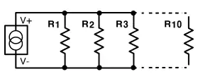
R total= The total equivalent parallel resistance of the resistor array across the current source.
Introduction
What is a Current Divider?
Parallel circuits in which the source or supply current divides into a variety of parallel paths are known as current divider circuits. Both of the components in a parallel wired circuit have their terminals connected together and share the same two end nodes.
Parallel circuits are distinguished by the fact that, although different currents can flow through different branches, the voltage is shared by all linked paths. VR1 = VR2 = VR3... and so on. As a result, finding individual resistor voltages is no longer necessary, and branch currents can be easily calculated using Kirchhoff's Current Law (KCL) and, of course, Ohm's Law.
The current flowing through any branch of a parallel circuit can be calculated using this Current Divider Calculator.
When a circuit is connected in parallel, the total current from the power source is divided among the circuit's branches depending on the resistance values of each branch. Since current follows the path of least resistance, more current will flow through branches with lower resistance, while less current will flow through a branch with high resistance.
Mastering the Current Divider Calculator
Understanding how current splits in a parallel circuit is essential for effective circuit design. Our calculator applies the standard Current Divider Rule to simplify this process for you.
The Current Divider Formula
To find the current flowing through a specific branch, we use the following equation:
Where:
- : Current flowing through the specific branch.
- : Total source current entering the node.
- : Equivalent parallel resistance of the entire circuit.
Step-by-Step Guide
- Input Data: Simply enter the total source current () and the resistance values for each resistor in your parallel circuit.
- Automatic Calculation: The tool automatically computes the equivalent resistance and the resulting current for each individual branch.
- Variable Branches: Whether you are analyzing a simple 2-resistor circuit or a complex network, this tool is flexible. It supports 2 to 10 branches—just enter values for the active branches and leave the unused fields blank.
The unit of this calculator's result is the one stated. Amperes (A), milliamperes (mA), or microamperes (A) may be used to express the resultant value.