Calculate bias conditions, current levels, voltage gain, and frequency response for wide-band differential amplifiers. Use the results to evaluate performance and guide your design decisions.
VB = VP*R2/(R1+R2)
VE = VB - VBE
IE = VE/RE
Alpha = Beta/(Beta+1);
IC = Alpha*IE
VC = VP - IC*RC/2
IB = IC/Beta
gm = Ic/25mA
re = Alpha/gm
rπ = Beta/gm
A = Alpha*rπ*RC/(Rs+2*rπ)/re
fP1 = 1/(2*π*(Rs||2*rπ)*(CBE/2+CBC))
fP2 = 1/(2*π*RC*CBC)
fT = gm/(2π*(CBE+CBC))
The lower pole is dominant.
Introduction
This tool is designed to calculate critical performance metrics for wideband differential amplifiers, including current levels, bias voltage, gain, and frequency response.
A Wideband Differential Amplifier is an amplifier designed to maintain a precise amplification factor over a wide frequency range while providing high gain.
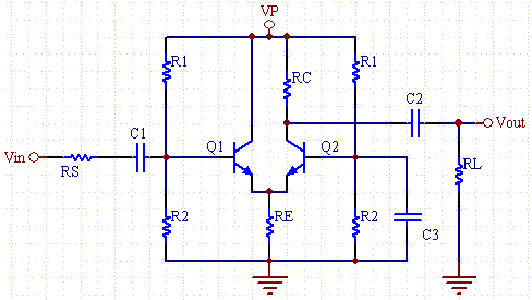
By using a specific configuration—tying the collector of the first transistor () to the base of the second () to signal ground—it is possible to overcome the Miller Capacitance limitations. The resulting gain-bandwidth product is orders of magnitude greater than that of standard common-emitter amplifiers.
A Differential Amplifier (or difference amplifier) is a circuit that amplifies the difference between two input signals while rejecting any signals that are common to both inputs. It is the fundamental building block of the Operational Amplifier (Op-Amp).
The Formula: The basic output equation is:
Where:
Ideally, if , the output is zero. The amplifier focuses purely on the gap between the two voltages.
Differential amplifiers are primarily used to suppress Noise.
The calculator determines critical parameters for wideband differential amplifier design, including transistor currents (IC, IE, IB), bias voltages (VB, VE, VC), voltage gain (A), and frequency response (fP1, fP2). It also computes transconductance (gm), input resistance (rπ), and other metrics based on resistor values, supply voltage, and transistor specifications.
By connecting the collector of Q1 and the base of Q2 to signal ground, the Miller effect is bypassed. This improves the gain-bandwidth product significantly compared to common-emitter amplifiers, enabling stable high-frequency operation.
You need resistor values (R1, R2, RC, RE), supply voltage (VP), transistor Beta (β), base-emitter voltage (VBE), current gain-bandwidth product (fT), and parasitic capacitances (CBC, optional CBE). Source resistance (Rs) and load resistance (RL) are also required for accurate gain and frequency response calculations.
Beta defines the DC current gain and directly affects collector current (IC = β × IB) and input resistance (rπ = β / gm). A higher Beta increases voltage gain and input impedance, but it also demands careful thermal and stability management to avoid drift or distortion.
The lower pole fP1 dominates because it originates from the input RC network (Rs in parallel with 2rπ, interacting with CBE/2 and CBC). This pole sets the -3dB bandwidth. The second pole fP2 comes from the output RC network and typically occurs at higher frequencies due to smaller time constants.
Resistor Color Code Calculator
Glofell’s Resistor Color Code Calculator decodes 4-band, 5-band, and 6-band resistors. Select each band to identify resistance, tolerance, and power rating for circuit work, repairs, or lab sorting.
Ohms Law Calculator
Glofell’s Ohm’s Law Calculator helps engineers and students quickly solve for voltage, current, resistance, and power. Provide any two known values to calculate the remaining parameters, making it a practical reference for circuit design, troubleshooting, and electronics learning.
Op-Amp Voltage and Gain Calculator
Calculate output voltage together with inverting and non-inverting gain for operational-amplifier circuits. Enter V1, V2, Vp, Vn, and resistor values R1 through R4 to obtain accurate results for circuit design, troubleshooting, and op-amp learning.
Inverting Op-Amp Resistor Calculator
Analyze an inverting operational-amplifier circuit by entering the desired gain, output voltage (Vout), R1 resistance, and input voltages V1, V2, Vp, and Vn. The calculator automatically determines the required R2, R3, and R4 resistor values, helping you design and verify inverting op-amp configurations.