Glofell's LED Series Resistor Calculator helps you find the current-limiting resistor needed to safely drive one or more LEDs. Enter the supply voltage, LED forward voltage, and operating current to get the recommended resistance and minimum power rating. For reliable operation and reduced heat, choose a resistor rated two to ten times above the calculated value.


Introduction
Every Light-Emitting Diode (LED) has a maximum current limit. Exceeding this limit, even briefly, can permanently damage the LED. Therefore, using a series resistor to limit current is a standard and essential practice.
Note: This resistive method is best for low-power indicator LEDs. High-power LEDs (like those used in lighting) typically require a dedicated switching current regulator.
To calculate the required resistance, simply subtract the LED's forward voltage from the power supply voltage, then divide by the desired current.
Where:
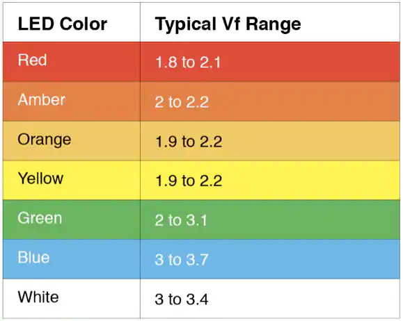
The voltage drop across an LED depends on the semiconductor material used to produce its color.
| LED Color | Typical Voltage Drop () |
|---|---|
| Infrared | 1.2V - 1.6V |
| Red | 1.8V - 2.2V |
| Orange / Amber | 2.0V - 2.2V |
| Yellow | 2.0V - 2.4V |
| Green | 2.0V - 3.0V |
| Blue | 3.0V - 3.4V |
| White | 3.0V - 3.6V |
For LEDs in series, multiply the forward voltage of one LED by the total number of LEDs to get the total voltage drop. Subtract that from the supply voltage, then divide by the desired LED current. The result is the required series resistance.
Check the LED datasheet for its forward voltage and recommended current (typically 10 to 20 mA). For example, an ultra-bright blue LED with a 9V battery may have a forward voltage of 3.2V and a typical current of 20mA. The required resistor would be (9V - 3.2V) / 0.02A = 290 ohms, so choose the closest available standard value.
In most cases, yes. An LED is a current-driven component, and a series resistor (often called a ballast resistor) sets the operating current. If the supply voltage exactly equals the LED's forward voltage and the supply is current-limited, a resistor may not be required. Otherwise, each LED or series string should have its own current-limiting resistor.
You can operate an LED from 220V AC by placing a capacitor in series to limit the current; unlike a resistor, the capacitor does not heat up significantly. A Zener diode is often added to protect the LED from high voltage. During the positive half-cycle, the Zener clamps the LED and series resistor to about 2.7 volts.
Connecting an LED directly to a voltage source without a current-limiting resistor allows too much current to flow. The LED may appear very bright for a short time, but it will quickly overheat and burn out.
The forward voltage of an LED typically ranges from 1.8V to 3.3V, depending on its color. A red LED usually drops around 1.7–2.0V, while a blue or white LED may drop about 3.0–3.3V because the voltage drop increases with the band gap energy.
It doesn't matter electrically. The resistor can be placed on either side of the LED in a series circuit because the current flowing through the circuit is the same, so the LED remains protected.
If you know the total current and the applied voltage, use Ohm's Law: R = V / I. For example, if a circuit has 9 volts across it and a total current of 3 amps, the total resistance is 9V / 3A = 3 ohms.
The most reliable method is to check the LED datasheet. You can also measure the forward voltage with a multimeter using the diode test function, or connect the LED in series with a battery and a potentiometer. Start with a high resistance and slowly decrease it until the LED reaches a comfortable brightness; the voltage across the LED at that point is its approximate forward voltage.
To reduce a voltage by half, create a voltage divider using two resistors of equal value in series, for example two 10 kΩ resistors. The output taken between the two resistors will be half the input voltage.
Resistor Color Code Calculator
Glofell’s Resistor Color Code Calculator decodes 4-band, 5-band, and 6-band resistors. Select each band to identify resistance, tolerance, and power rating for circuit work, repairs, or lab sorting.
Ohms Law Calculator
Glofell’s Ohm’s Law Calculator helps engineers and students quickly solve for voltage, current, resistance, and power. Provide any two known values to calculate the remaining parameters, making it a practical reference for circuit design, troubleshooting, and electronics learning.
Op-Amp Voltage and Gain Calculator
Calculate output voltage together with inverting and non-inverting gain for operational-amplifier circuits. Enter V1, V2, Vp, Vn, and resistor values R1 through R4 to obtain accurate results for circuit design, troubleshooting, and op-amp learning.
Inverting Op-Amp Resistor Calculator
Analyze an inverting operational-amplifier circuit by entering the desired gain, output voltage (Vout), R1 resistance, and input voltages V1, V2, Vp, and Vn. The calculator automatically determines the required R2, R3, and R4 resistor values, helping you design and verify inverting op-amp configurations.