Ohms Law Calculator
Glofell’s Ohm’s Law Calculator helps engineers and students quickly solve for voltage, current, resistance, and power. Provide any two known values to calculate the remaining parameters, making it a practical reference for circuit design, troubleshooting, and electronics learning.
Introduction
Ohm's Law: Guide & Calculator Overview
Introduction
For certain conductors of electricity, the electric current passing through them is directly proportional to the voltage applied. This relationship relies on the fact that the drift velocity of charges through the material is proportional to the electric field in the conductor.
The resistance is the ratio of voltage to current. If this ratio remains constant over a broad range of voltages, the material is considered "ohmic." If the resistance of a substance is known, the current can be predicted using the fundamental relationship known as Ohm's Law.
Overview of Ohm's Law Calculator
An Ohm's Law Calculator is a handy tool for determining the mathematical relationship between voltage, current, and resistance across a conductor. These formulas are fundamental in electrical engineering and electronics. Understanding how to calculate these values, along with power, is essential for analyzing electronic circuits.
Ohm's Law Explanation
What is Ohm's Law?
Ohm's Law asserts that if all physical parameters (such as temperature) remain constant, the voltage across a conductor is directly proportional to the current flowing through it. Resistance () is the constant of proportionality in this equation, measured in units of ohms ().
How Does It Work?
Ohm's Law defines how current flows through a resistance when a distinct electric potential (voltage) is applied. This is often compared to water flowing through a pipe:
- Voltage (): Represents water pressure.
- Current (): Represents the volume of water flowing.
- Resistance (): Represents the size of the pipe.
Higher pressure (voltage) or a wider pipe (lower resistance) results in more water flow (current).
Ohm's Law Formulas (DC)
The relationship describes the link between Voltage (), Current (), and Resistance ().
1. Voltage Formula The voltage in volts () is equal to the current in amps () multiplied by the resistance in ohms ():
2. Power Formula The power in watts () is equal to the voltage multiplied by the current :
3. Resistance Formula Resistance can be calculated as the quotient of voltage and current:
4. Current Formula Current is equal to voltage divided by resistance:
Note: Ohm's law strictly applies to ohmic materials (like metals and ceramics) under constant conditions. Non-linear devices like semiconductors and insulators may not follow this linear relationship strictly.
AC Ohm's Law Formula
In Alternating Current (AC) circuits, resistance is replaced by Impedance ().
Voltage in AC:
(Where is Impedance in )
Complex Power () in Volt-Amps ():
Visual Aids: The Triangle and The Wheel
Ohm's Law Triangle
The Ohm's Law Triangle is a visual tool to help remember the three main formulas. Voltage () is always at the top, with Current () and Resistance () at the bottom.
- To find Resistance (): Cover . You see over .
Ohm's Law Wheel (Power Wheel)
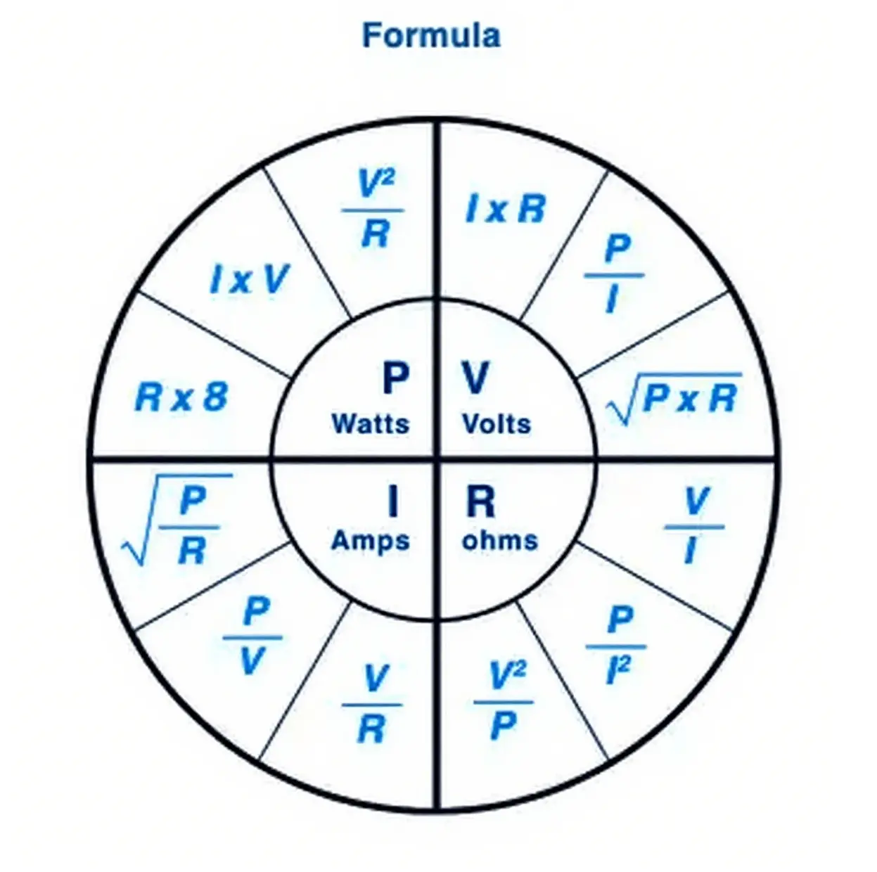
The "Formula Wheel" combines Ohm's Law with the Power formula () to show the relationships between Power (), Current (), Voltage (), and Resistance (). This creates four quadrants, each offering three formulas to solve for a specific variable.
How to Use the Power Wheel
- Identify the Target: Decide which variable you need to solve for (P, R, I, or V).
- Identify Knowns: Determine which two variables you already know.
- Select Formula: Look at the quadrant for your target variable and select the formula that uses your two known variables.
- Solve: Plug in your numbers and calculate.
Tip: Always ensure units are consistent (e.g., convert Milliamps to Amps or Kilohms to Ohms) before calculating.
Practical Example
Scenario 1: You have a 120 Volt () light bulb that draws 0.625 Amps () of current. What is the resistance?
- Formula:
- Calculation:
- Result: The resistance is 192 .
Scenario 2: You know the current () and the filament resistance (). Can you find the voltage? Yes, using the Triangle:
- Formula:
How to Calculate Using Ohm's Law
You can determine the values in any circuit in three simple steps:
- List Known Values: Write down the variables you know (e.g., , ).
- Identify Unknown: Write down the variable you need to solve for (e.g., ).
- Apply Formula: Use the standard formula (or its variations) to solve.
Definitions:
- Current (): The flow of electrons, measured in Amps.
- Voltage (): The electrical pressure or potential difference, measured in Volts.
- Resistance (): The opposition to current flow, measured in Ohms.
Conclusion
Ohm's Law is straightforward yet critical for all circuit design. By knowing just two of the three variables, you can easily determine the third. This cornerstone of electrical engineering underpins the inner workings of every circuit, from the simplest flashlight to the most complex motherboard.
More Electronic Conversion and Calculators
- dBm to Watts Calculator
- BJT Cascode Amplifier Calculator
- SMD Resistor Code Calculator
- Resistor Color Code Calculator
- Parallel and Series Resistor Calculator